[Wotian share] Temperature transmitter and its application
From: Issued date 2020.03.06 Back
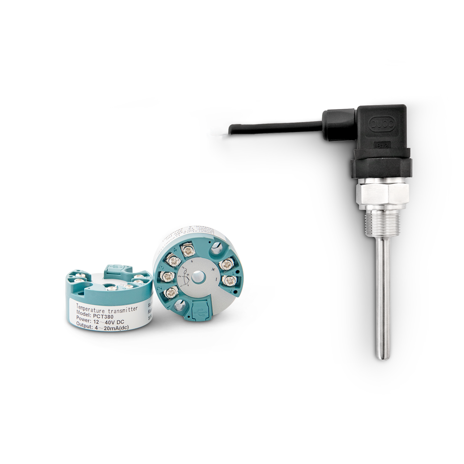
The temperature transmitter is a very important part of the process control instrument. It is not only used directly for temperature measurement and control, but also used as a calibration parameter in the measurement and control system of some related parameters to achieve accurate measurement and control.
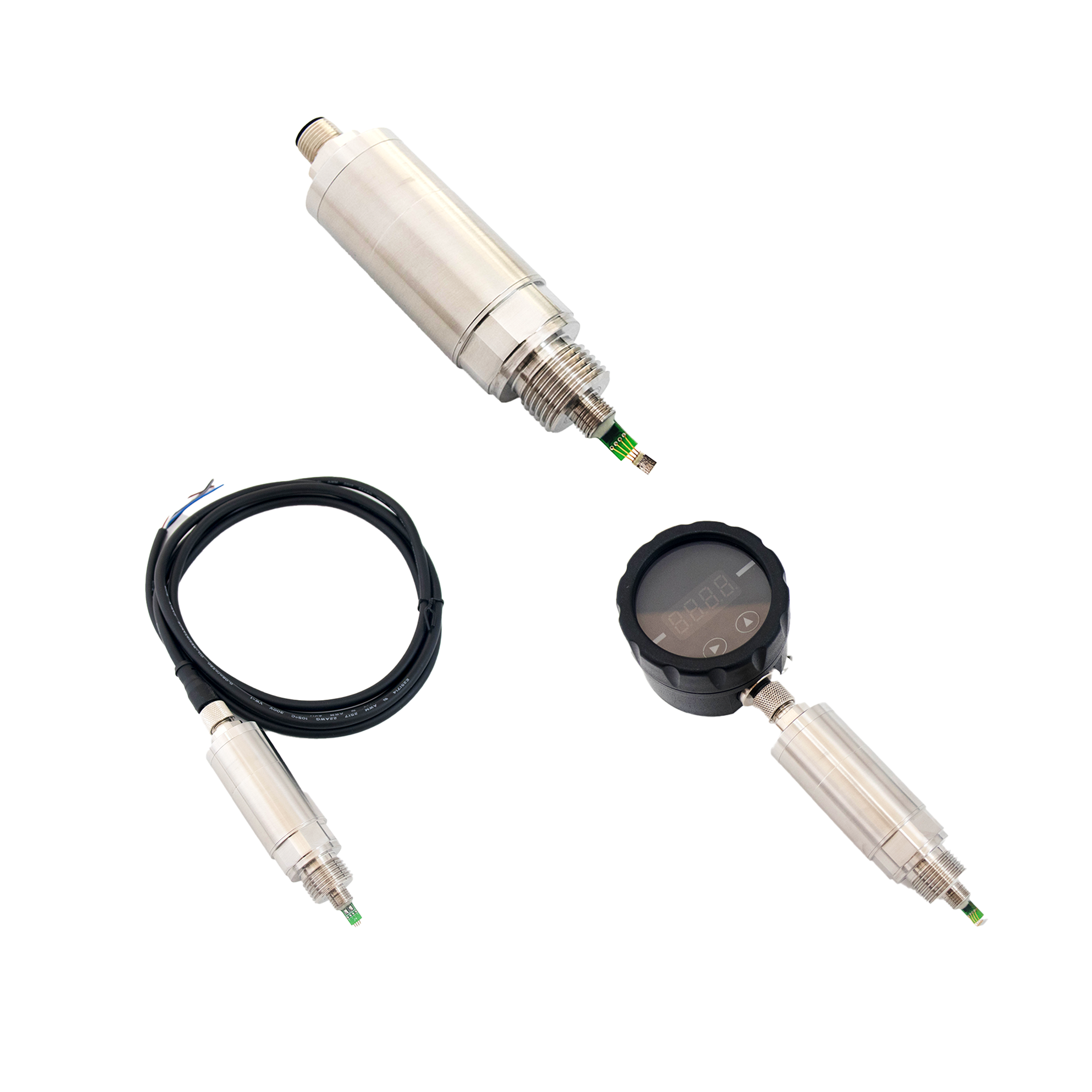
Generally speaking, the temperature transmitter does not include a temperature sensor (primary instrument). Its function is only to amplify the small electrical signals (voltage, current, resistance) sent by the temperature sensor and convert them into standard electrical signals (0 ~ 10mA, 4-20mA or 0-10V, 1-5V, etc.) output. The amplified and standardized signal is beneficial for long-distance transmission and subsequent data processing by the instrument. At present, an integrated temperature transmitter (also called an integral temperature transmitter) is popular in China. This type of transmitter includes a primary instrument (such as an industrial thermocouple and an industrial platinum resistance). The line and the primary instrument are assembled together to provide more convenient conditions for field installation and use. The output signals are generally two-wire 4-20mA current signals. The input signal of the temperature transmitter is essentially a weak change in voltage, current, and resistance. Therefore, it can actually cooperate with a sensor whose output is a change in voltage, current, or resistance to form a variety of non-electric parameters. Transmitter, such as pressure, differential pressure, displacement, angle, etc. Because the temperature transmitter is an electric power input, and the input signal is small, (the voltage signal is generally millivolt level, the current signal is microampere level resistance signal is ohmic level), the conversion accuracy is high, and the input and output signal transmission distance may be far. Input and output signals generally require non-linear correction, so it has stricter requirements than other transmitters.
General technical requirements for temperature transmission
There are many types and categories of temperature transmitters, but the most basic technical requirements are the prerequisites to ensure their normal work.
1.Technical indicators related to accuracy Generally, the technical indicators related to accuracy should include four items: basic error limit (that is, the maximum allowable basic error), end-group consistency error, backlash, and repeatability error.
Basic error limit
The maximum measurement error determined by the meter under the specified reference operating conditions.
End-group consistency error
The maximum deviation between the actual characteristic curve and the given curve when the given curve and the actual characteristic curve (the average of the readings of the upper and lower strokes) overlap on the upper and lower limits.
Return difference
The difference between the average error of the upper stroke and the average error of the lower stroke corresponding to the same input signal value.
Repeatability
Consistency of the output signal corresponding to the same input signal applied multiple times in the same stroke direction when moving at the full stroke under the same working conditions.
2. Technical requirements related to impact
The indicators of the accuracy of the instrument are measured under a nearly ideal working condition, but the actual working conditions deviate from the ideal working condition. Therefore, the adaptability to changes in working conditions is a very important measure of the performance of the instrument. Important indicators. The so-called influence amount refers to various factors that change working conditions. The extent to which these factors affect the output value of the temperature transmitter. A good transmitter should have a strong resistance to the effects of these factors in order to obtain better results.
Impact of changes in dynamic conditions
Power condition refers to the power supply of the temperature transmitter. There are usually two types of 220VAC and 24V.DC.
Influence of power supply voltage and frequency fluctuation
For a 220V.AC-powered temperature transmitter, when the voltage and frequency fluctuate within the range specified by the manufacturer, the general output change should not exceed the basic error limit of the meter. The same rules apply to instruments operating at 24V.DC.
Power reverse protection
For DC-powered instruments, they must have reverse power protection. Even when the power supply polarity is reversed, the instrument will not be damaged. After the power supply returns to normal, the performance of the instrument remains unchanged.
Effect of output load change
The output load of the instrument should be able to vary within the range specified by the manufacturer, and the effect on the output should not exceed half of the basic error limit of the instrument, or as specified by the manufacturer.
Impact of interference
There are various kinds of interference in the instrument work site, and they must have a certain resistance to these interferences. These interferences mainly include common mode interference, series mode interference, radio frequency interference, electrostatic interference, and external magnetic field interference. The anti-interference indicators, test methods, relevant standards and manufacturers have detailed regulations. It is difficult for users to test these indicators, but users can emphasize to the manufacturer when ordering according to the specific conditions of the site. Item requirements.
Grounding effect
When the temperature transmitter is in use, both the input signal and the output signal may be connected to the earth or at the same time there is a requirement for earth connection. Therefore, input or output or both input and output should be allowed to be grounded at the same time. Sometimes this situation will affect the output signal of the transmitter. For a good temperature transmitter, this effect will be controlled within the range of 0.1% to 0.2% of the range. It must be noted that for products that are not isolated from the input and output, the input and output cannot be grounded at the same time.
Ambient temperature effect
The impact of ambient temperature changes on the output of the instrument is also called temperature drift (temperature drift), which is an important indicator for temperature transmitters. It is usually specified in the operating temperature range specified by the manufacturer. When the ambient temperature changes by 10 ° C, the output changes as a percentage of the range. Generally, it does not exceed one half of the basic error of the table. set.
Influence of source impedance
Source impedance refers to the internal resistance of the signal source. For transmitters with thermocouple or millivolt signal input, the main effect is the resistance of the thermocouple extension cable. Due to the long transmission distance and the high resistance of the extension cable, the resistance of the extension cable is large, which will give the transmitter output affect. The specific regulations depend on the manufacturer's instructions. When the user is using, pay attention that the resistance value of the thermocouple extension line does not exceed the manufacturer's requirements. For the transmitter with thermal resistance input, the change of the line resistance will bring a large measurement error. Generally, manufacturers will specify the size of the line resistance, and even equipped with an adjusted resistance. A good quality thermal resistance temperature transmitter should be as long as the thermal resistance is three-wire or four-wire, and the resistance of each lead is equal to the maximum resistance value specified by the manufacturer. It is worth noting that users must strictly adopt the three-wire or four-wire connection method according to the requirements of the manufacturer, and it is not appropriate to use the two-wire connection method that only draws two wires from the primary component terminal.
Stability requirements
Initial drift
Start-up drift refers to the output change of the transmitter within a short period of time after power-on. The specific test method is: before the test, the transmitter is left under the test environment for 24 hours, and the power is not connected. The transmitter is connected to the power supply and applied 10% of the range input signal, and each record the output signal value after 5 minutes, 1 hour, and 4 hours, and then disconnect the input signal and power, in the test environment · 61 · 1997 2nd After the industrial instrument and automation device is left for 24 hours, the above test is repeated by sending 90% of the input signal of the range. Compare the output value measured after 5 minutes and 1 hour with the output value measured after 4 hours. The maximum difference is the starting drift value.
Long-term drift
The transmitter is left for 24 hours under the reference atmospheric conditions, and then sent into the 90% constant range input signal for 30 days. Test the lower limit and range of the transmitter. Observe and record the output value every day during the test. Immediately after the test, test the lower limit and range of the transmitter. Changes in the lower limit and range before and after the test are long-term drift.
Requirements on the mechanical properties of the transmitter
The requirements for the transmitter's mechanical performance mainly refer to the transmitter's resistance to transportation shock and its resistance to shock and vibration.
Other performance requirements
Output AC component
0%。 The effective value of the AC output of the transmitter should not be greater than 1.0%.
Insulation resistance and strength
The insulation resistance of each terminal of the transmitter to the shell should not be less than 50MΩ, and it can withstand the insulation strength test of at least 500V and 50Hz.
For instruments with input and output isolation, the insulation resistance between the input and output terminals should not be less than 50MΩ, and they should be able to withstand the same insulation strength test.
Effects of open and shorted inputs
There may be open or shorted input terminals during the use of the meter. A fully functional transmitter should not only have an alarm function for open or shorted input terminals, but the accuracy of the meter should not be affected after the input returns to normal. The above only exemplifies the most important part of the general technical requirements for temperature transmitters, and does not include the requirements for dynamic characteristics. For detailed requirements, please refer to the relevant technical standards and relevant documents of the manufacturer.

